Flue Temperature Monitor and Alarm
A safety monitor/alarm/cutout to prevent burning of high-temperature RTV gaskets for Wood Gun Boilers
The Problem
We have an E140 Wood Gun boiler, installed in 1992. The Wood Gun is a "forced draft" wood-burning boiler, using a 3/8 HP motor-driven fan to force the draft. As a result of the "forced draft", the flue runs under a small amount of pressure and each joint must be sealed to keep exhaust gases and smoke in the flue until it reaches the chimney.
From the time we purchased the boiler, we've used Permatex® High-Temp Red RTV Silicone Gasket to seal joints in the flue. It's rated for temperatures up to 650° Fahrenheit (all temperatures will be expressed in Fahrenheit degrees unless otherwise stated), adheres well to our stainless steel flue pipes, and remains flexible. Over the years, we've come home a few times to find that the Permatex gaskets had turned into white powder and that the joints were no longer sealed. This seemed to happen when the flue got too hot (apparently due to a small fire in the flue, which is remedied by cleaning the flue) and we accepted this as a fact of life until it happened one night when we were home and found that the material actually caught on fire when the flue got too hot. Living in an old house, this was too scary to ignore and we started looking into alternatives.
We found some stainless steel ceramic sealants from Cotronics, such as their 7032 putty that is rated to 2000°. We've been able to use the 7032 putty for some stationary joints, but still need flexible seals for other joints. Not being able to find sufficiently high-temperature, flexible sealants, we took another tack, The idea was that if we could detect high-temperatures on the flue, we could power down the boiler long before the gaskets failed. The Flue Temperature Monitor and Alarm was designed a built to provide this function.
Theory and Design
Design Assumptions/Constraints
- Overly-high flue temperatures result from small fires in the flue. If we can power down the boiler when a fire is detected, the fire will be quenched, directly addressing the over-temperature problem that causes gaskets to horribly fail.
- Normal flue temperatures during firing are around 250° when burning wood and around 325° when burning oil. If we can detect over-temperature conditions 100°-200° before the Permatex gasket failure temperature of 650°, we should be able to power down the boiler and stop the fire.
- We need to reliably read the flue temperature in several places in real-time to make decisions.
- In the event of an over-temperature condition, we need to interrupt power to the boiler and activate an audible alarm to let us know that we need to clean the flue.
- The solution needs an adjustable "trip point" temperature that can be set as low as needed to detect problems, yet be adjustable to avoid false alarms.
- The solution should be able to function using either Celsius or Fahrenheit degrees.
- The solution must be minimally invasive to the boiler and not interfere with its mechanisms.
- The solution must not interfere with maintenance of the oil burner.
- The solution should be easy to remove from the boiler if required.
Inputs/Outputs
- Input will be taken directly from the flue pipe in several locations using Type K thermocouples, which function over a range of -328° to 2282°. The thermocouples will be read by a microcontroller, which will determine when and if an over-termperature event has occured.
- Power to boiler will be dropped by interting a relay between the boiler and the breaker panel, allowing all power to be removed from the boiler at will (Note: The relay will be placed between the breaker panel and the "oil-burner reset" discussed elsewhere on this site).
- The highest current flue temperature reading above 120° will be displayed on a large numeric LED display in the living area of the house to indicate the health of the fire when burning wood.
- The microcontroller will be capable of being polled across a network to record flue temperatures and boiler state, to develop boiler operation reports.
Proposed Operation
- Four Type K thermocouples will be read by circuitry that provides real-time digital temperature readings to a microcontroller.
- The microcontroller will also read a "trip point" setting from digital thumbwheel switches to determine the alarm temperature.
- If any thermocouple reads a temperature greater than the "trip point" for more than 10 seconds, the microcontroller will energize a relay which will:
- Interrupt power to the boiler
- Provide power to an audible alarm.
- After an over-temperature event, the microcontroller keep the relay energized (and the thus boiler powered down) until it's software is reset, either by cycling microcontroller power or by pressing a "reset" button.
Schematic and Major Components
System Board, schematic, 27KB PDF file. The heart of the system is a 40-pin Basic Atom microcontroller. The 40-pin model was chosen to support the large number of connected devices. Basic Micro's BasicATOM Super ProtoBoard serves as the System Board, providing 5VDC power and Basic Atom signals to the other components. Additional components on this board are DIP sockets to support ribbon cables connecting to other modules. One of the ribbon cables connects directly to a 2x16 LCD display on the Control Panel.
Sensor Board, schematic, 27KB PDF file. This board carries the interface circuitry for four (4) Type K thermocouples. Each thermocouple connects through a Type K miniature connector to a Maxim MAX6675 Type K Thermocouple Converter Chip. The negative side of each thermocouple connector is connected to system ground to allow the MAX6675 chips to detect open thermocouples. The MAX6675 converts Type K thermocouple voltages to a digital Celsius temperature reading over a range of 0°C to 1024°C, forwarding readings via a Serial Peripheral Interface (SPI). The micrcontroller triggers each MAX6675 to returns it's readings every second. To use Fahrenheit degress, the microcontroller software converts Celsius readings to Fahrenheit using the standard conversion formula.
Interface Board, schematic, 79KB PDF file. This board provides several functions:
- Circuitry to convert the 8 pins of a 2-digit BCD thumbwheel switch ("hundreds" and "tens" digits - "ones" digits are set to zero in software) to an SPI interface to reduce the number of Basic Atom pins required to read the thumbsheel switch. The thumbwheel switch is located on the Control Panel. I bought the following thumbwheel switch parts from Mouser Electronics:
- P/N 611-3U0210002, BCD Decimal Pushwheel Switch with Dust Lens, 2 each.
- P/N 611-113B02000, BCD Decimal Pushwheel Switch-Left End Cap, 1 each.
- P/N 611-114B02000, BCD Decimal Pushwheel Switch-Right End Cap, 1 each.
- Circuity to interrupt power to the boiler. The line from the System Board connects to the gate of an IRF820 MOSFET. When the line goes high, it causes the MOSFET to conduct, engaging the 12VDC relay , which in turn engages a high-current 120VAC relay that interrupts boiler power and powers up the audible alarm. I bought the following replay parts from Mouser Electronics:
- P/N 653-G2R-2-SN-DC12S, Omron G2R Series Relay, 5A Contacts DPDT, 12VDC Coil, 1 each.
- P/N 653-P2RF-08-E, Socket for Omron G2R-2S Relays, Screw Terminals, 1 each.
- P/N 653-G7J-2A2BBW-AC1, Omron G7J Series Relay, 25A Contacts DPST-NO/DPST-NC, 120 VAC Coil, Screw Terminals, with Mounting Bracket, 1 each.
- A 3-pin jumper to tell the microcontroller whether or not to convert MAX6675 readings from Celsius to Fahrenheit. Shorting the center pin high signals Fahrenheit and shorting it to ground signals Celsius. The 3 jumper pins are wired to a SPDT switch located on the Control Panel. The microcontroller software must be reset to accept a change to this setting as the line is only read at system start.
- Circuitry to covert TTL serial signals to RS-232 signals, to talk to external devices. A MAX232 chip converts the following signals:
- The Basic ATOM Hardware Serial port lines are converted to connect to a Siteplayer Telnet device, which allows networked sytems to poll readings from the microcontroller using the following Command/Reponse Specification, 7KB PDF file.
- A Basic Atom "Software" Serial port that connects to the numeric LED display in the living area of the house. As the LED display only "listens" for commands and has no ability to transmit data pin, only the "transmit data" is connected to the remote display.
Power Supply, schematic, 25KB PDF file. Power for the electronics is provided by an Omron 12VDC power supply. A Transtronics battery backup relay provides battery backup to cover short-term power outages. In order to keep the 12V, 1AH AGM battery charged, the power supply was adjusted to provide 13.8VDC. The circuitry requires 12VDC, so 2 rectifier diodes are placed in series with the power supply to drop the voltage back to 12VDC. A fixed 8VDC reduces the voltage to the System Board to reduce heat dissipated by the 5VDC regulator on that board, as well as providing power to the Siteplayer Telnet device.
Sensor Wiring, schematic, 11KB PDF file. To bridge the distance from the Type K thermocouple sensors and the Sensor Board, I used Type K extension wire, terminated in Type K miniature connectors. The actual thermocouple sensors were Omega Engineering P/N WTK-HD-72-OSTW-M, which is a heavy-duty armored assembly with the thermocouple welded to a washer for "Bolt-on" attachment.
Remote Display Wiring, schematic, 47KB PDF file. The wiring the Remote Display required that both signal and power be carried to the display unit. The display itself is made up of two Velleman K8063 "2 Modular Digits With Serial Interface" kits. Each digit functions independently, with an individual address, and monitors a 2400bps RS-232 line for specific-digit and global commands. I determined that I could power all four digits at maximum power over 3 pairs of a CAT 5 cable and still be within 802.3af "Power over Ethernet" specs, although the display will only operate at full power during an over-temperature event.
Microcontroller Software
The software (Atom Basic, 33KB) is divided into the following functions:
- Initialization.
- Variables are definied and initialized.
- The LCD display is initialized.
- A system uptime counter (seconds) is inititialized.
- The temerpature scale setting (Celsius/Fahrenheit) is read and fixed.
- The Basic Atom Hardware Serial prot is initialized to 9600bps.
- An initial "Set Point" reading is taken.
- The alarm state to forced to off (i.e., normal operation).
- Main loop for monitoring, running once per second. The main loop calls a series of subroutines to execute the various required functions. The following actions happen during each loop:
- Accept and respond to commands from the network (Hardware Serial Port)
- Check the "Set Point" thumbwheel switches and process changes.
- Take readings from all 4 thermocouple sensors.
- Determine if any sensors exceed the "Set Point". If any sensors exceed the "Set Point", power down the boiler and set the audible alarm. There is nothing in the software to reverse this action. The alarm can only be reset by power cycling or by pressing the Reset button.
- Update the LCD display.
- Update the large LED display in the living area of the house.
- Update the system uptime
- Pause until the rest of the second has passed (wait approximately 890mS).
- Note that in Alarm mode, the only thing that changes is the Alarm state. The system continues to run and monitor, but the alarm state will be maintained until reset by power cycling or by pressing the Reset button.
Construction and Installation
System Enclosure
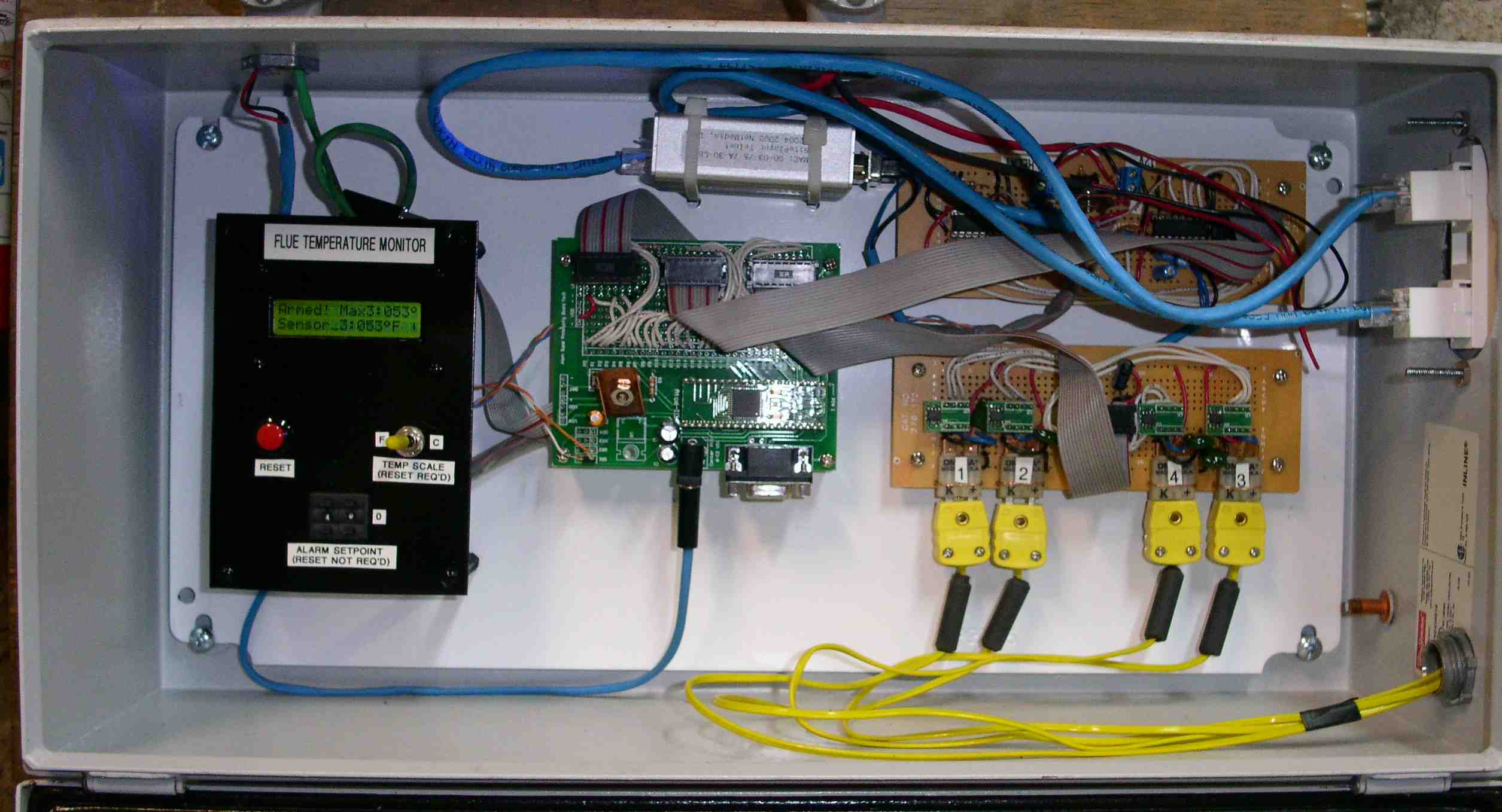
The following image shows the system enclosure with the following items (from the left):
- Control Panel, housing the:
- LCD Display. The top line of the LCD display shows the system status (in this case "Armed!") and the shows the number and temperature of the sensor with the highest current temperature reading. The last digit is a "spinner" that shows the unit is running. The second line cycles through the current temperature of each of the 4 sensors, as well as the Set Point.
- Reset Button. This button resets the microcontroller program.
- Temperature Scale Switch. This switch is read at system start and determine whether readings will be Fahrenheit or Celsuis degrees.
- Set Point thumbsheel switches. These switches set the "tens" and "ones" digits of the set point, from 0° to 990°.
- System Board, housing the Basic Atom Microcontroller and supporting circuitry, as well as DIP sockets for ribbon cable connections to the LCD Display, Sensor Board, and Interface board.
- Siteplayer Telnet device (silver box above the System Board) that allows the microcontroller software to be queried across a network.
- Interface Board (top)
- Sensor Board (Bottom), with 4 Type K Extension wire connections coming in from the Thermocouples.
- Cat 5 cable connections to the house network and LED display in the living area.
Power Enclosure
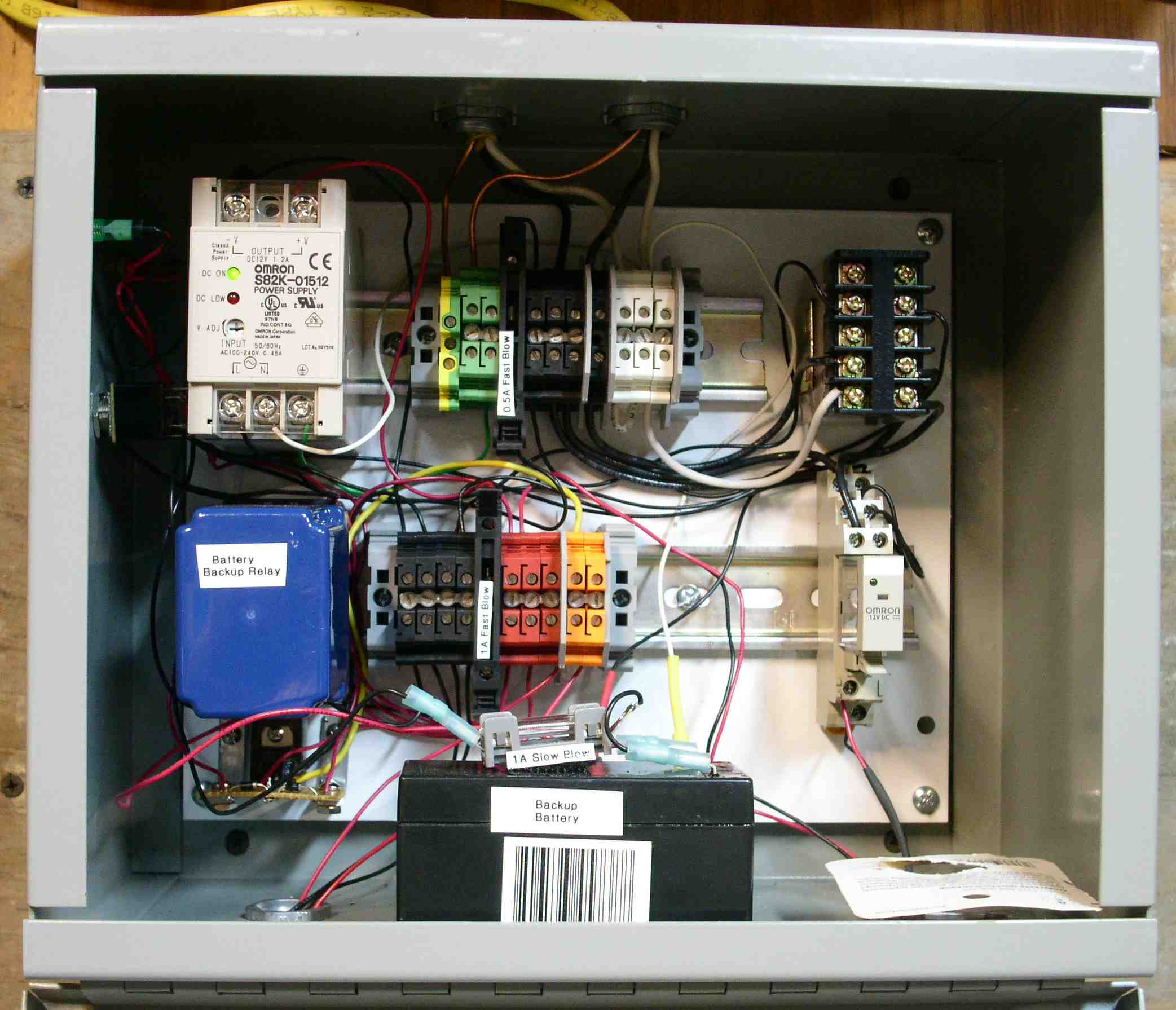
The following image shows the Power Enclosure with the following items (clockwise from the upper left):
- Omron 12VDC Power Supply,
- Green, Black, and White terminal strips for 120VAC Line power (these terminal strips are great, eventhough they cost a fortune).
- 120VAC relay that interrupts boiler power. The "normally closed" contacts of this relay are connected inline between the Breaker Panel and the Boiler.
- 12VDC relay, triggered by the microcontroller through a MOSFET and triggering the 120VAC relay to interrupt boiler power.
- 12VDC 1AH backup battery.
- DC terminal strips, with Black for ground, Red for 12VDC, and Yellow for 8VDC.
- 8VDC three-terminal regulator.
- Transtronics battery backup relay (the blue box).
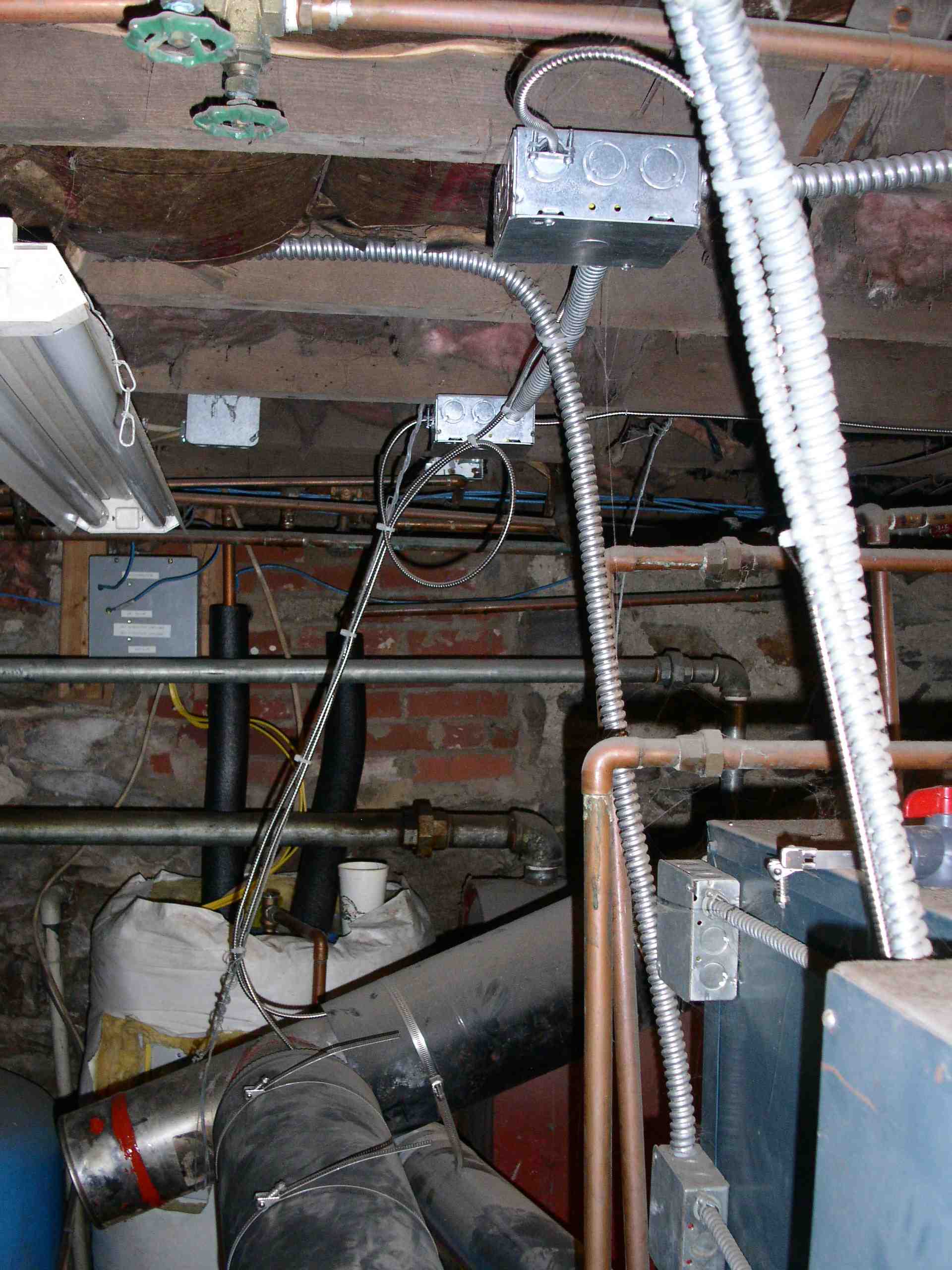
Thermocouple Installation
The following image shows the boiler with the Thermocouple cables (the small armored cables) running from the boxes attached to the floor joists and running under the flue pipe insulation. Inside the boxes, there are Type K connectors that interface the Thermocouples to Type K extension cable to go back to the Sensor Board (the yellow wires entering the lower right of the System Enclosure).
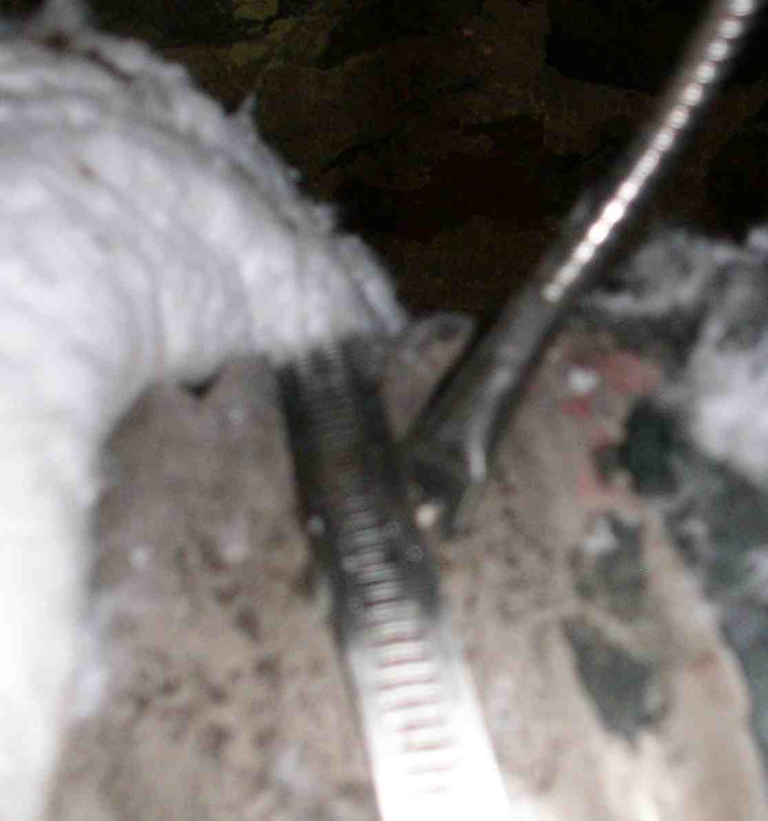
Here is a very badly taken picture of the acutal thermocouple attachment to the flue pipe. This was the only thermocouple of the four that is exposed and I couldn't get a good picture (this was the best). The washer attached to the thermocouple is clamped to the top of the flue pipe using a large "worm gear" type clamp to assure good thermal contact.
Operation
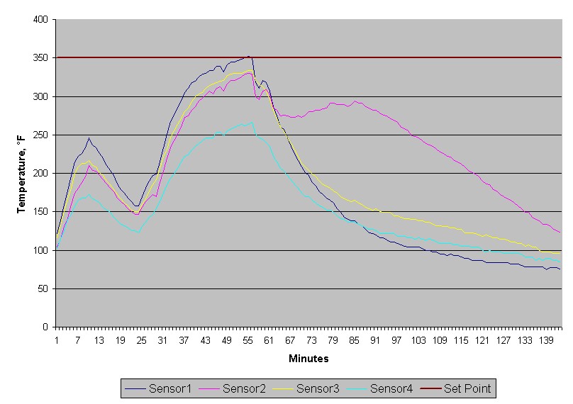
The system runs all the time, regardless of whether the boiler is turned on or off. It consumes little power, so it doesn't hurt anything to run. The graph below was taken from actual data queried across the network when we actually had a small flue fire dring operation. On the graph, the boiler is running at the start and cuts off at about 10 minutes. At 25 minutes, the boiler comes on again and the temperature of Sensor1 (the closest sensor to the boiler) increases until it crosses the Set Point (350°F) at about 56 minutes into the graph, and the system powers down the boiler (Note: this isn't necessarily a flue fire). The temperature of all sensors start dropping, but at about 70 minutes, Sensor2 start climbing again. With the other sensors falling, this is most certainly a small fire in that area of the flue. At about 85 minutes, the fire apparently plays itself out and the Sensor2 temperature starts falling. The system shut down the boiler with all deals intact and a good flue brushing prevented this from happening again.
The only problem I've had is that lightning in the area has caused blown fuses and damaged the Siteplayer Telnet device. After replacing this $100 box twice, I purchased a Trendnet Power over Ethernet injector and powered the newest Siteplayer Telnet model (now with PoE) from the network vice the system power supply. I haven't figured out why power surges damaged the Siteplayer Telnet box but not the circuitry. Go figure.
Because the MAX6675 chips read in Celsuis and the Basic Atom software doesn't support floating point math, the Celsius-to-Fahrenheit conversion makes for interesting jumps in temperature readings as the flue pipe heats up. While the Celsius number increases one degree at a time, the Fahrenheit reading sometimes jumps two degrees because the math truncates fractional values rather than rounding. A small perturbation...
Because the system runs all the time, the LED display in the living area also provides temperature readings that provide a really good indication of the health of the fire when burning wood. It gives a really good indication of when the fire needs attention, such as adding wood or stirring it up some.
Cost
The labor was all mine, so the total cost was materials. The material cost was about $1100, mainly because I was buying small quantities at retail prices and paying shipping. If I were a company, I could buy at wholesale (at least 50% off) and if I bought in quantity (like a manufacturer), I could probably get another 25% to 50% off wholesale. A bit expensive, bit worth it to have positive protection against the flue seals going up in flames.
Disclaimer. Any and all opinions expressed on this page are solely those of the author. The author accepts no responsibility for the accuracy of data provided on this web site, nor does the author accept any responsibility for the use and /or misuse of information provided on this web site. It is the full and sole responsibility of the user to determine whether and/or how best to use the information provided within their own circumstances, and it is the full and sole responsibility of the user to accept any and all benefits and/or consquences of their actions. Please see my Privacy Policy.
Copyright 2001-2009, Tim Sharpe. You are free to use this information for personal, non-commerical use without restriction. All rights reserved for commerical, organizational, or government use. Questions or comments to tim@beaststwo.org. Flames to /dev/nul.