Front Drive Indicator for 4WD trucks
We have a 1997 Ford F-250 4x4 with Automatic Locking Hubs. These hubs have a track record of failing, and we've had to replace them twice already (both times the hubs wouldn't unlock). Even with new hubs, there's always the question of whether they really unlocked, since to unlock them you put the transfer case into 2WD, back up a distance, and hope.
After replacing the hubs for the second time, we decided it would be nice to have a way to tell when the front hubs were engaged. When in 4WD, both front wheels are "locked" together; therefore, when in 2WD with one or both hubs are locked, the front driveshaft will turn. I built a device to sense front driveshaft motion and provide an indication inside the vehicle.
Assumptions:
- The device should monitor the front driveshaft whenever the truck is driven.
- The device flash a light inside the cab whenever the front driveshaft rotates.
- The light should be on when the front driveshaft is stationary and flash when the front drive rotates (by having light normally on, you can tell the difference between the front driveshaft not turning and a blown fuse).
About the circuit:
The circuit (schematic, pdf format) consists of a Hall Effect sensor (a magnetic sensor that detects movement of ferrous metals) and two 555 timers. The first 555 timer operates in monostable mode with an on-time of about 1 second. The second 555 timer operates in astable mode at about 4Hz. Normally, the first 555 timer inhibits oscillation of the second 555 timer. When the first 555 timer receives a pulse from the Hall Effect sensor, it raises it's output and permits the second 555 timer to oscillate for about 1 second. An LED assembly (with internal resistor for 12V operation) is connected between +12V and the output of the second 555 timer, so that the second 555 timer selectively breaks/makes the ground path for the LED.
This is a faily simple circuit, and almost anybody who works or plays with electronics can build it.
Parts:
- 1 ea Cherry P/N GS100701 Hall Effect geartooth sensor. I bought mine from Mouser Electronics, P/N 540-GS100701, for about $25.
- 2 ea 555 timers.
- 1 ea 12V LED assembly, Radio Shack P/N 276-271.
- 1 ea 10uf capacitor, at least 25WV
- 2 ea 1uF capacitors, at least 25WV
- 3 ea 0.1uF capacitors, at least 25WV
- Assorted resistors, 1/4Watt (see schematic)
- 1 ea 1N4001 diode (for polarity protection)
- Fuse holder with 0.3A fuse (the circuit draws about 0.05A, but 0.3A was the smallest fuse I could find)
- Assorted hardware (enclosure, connectors, wire, etc)
I used a Hall Effect sensor so that I could sense movement using the irregular shape of U-Joints on the front drive shaft. The sensor contains a reference magnet (it does exhibit magnetic attraction) and identifies motion by sensing time-varying changes to it's magnetic field. When ferrous metal moves close enough to the front to significantly alter the magnetic field, the sensor shunts the output to ground. A reed switch could be used instead, but requires a magnet to be attached to the shaft. If you wish to use a reed switch, connect it to the Yellow and Black sensor wires, as shown in the schematic. I successfully tested Cherry P/N MP200701 (Mouser Electronics, P/N 540-MP200701, about $8) in my breadboard model. Either sensor will work and have the same dimensions. I prefer the Hall Effect sensor as it requires no magnet and because it has no moving parts (i.e., shouldn't wear out).
Assembled circuit:
I'll spare you having took at my horrible soldering. The completed module is shown below. I used a small enclosure that came with a circuit board (Radio Shack P/N 270-283). The perf/printed circuit board was serviceable, but also lent to nasty-looking construction (nasty enough that I don't want to open it again unless I have to, for fear I'll break it). I was able to mount the fuse holder (I used Radio Shack P/N 270-739) on the circuit board, so that everything except the LED and sensor are in the box. I used 18AWG automotive primary wire for the external connections and a liberal wrapping of electrical tape (visible) for strain relief where the wires exit the enclosure.
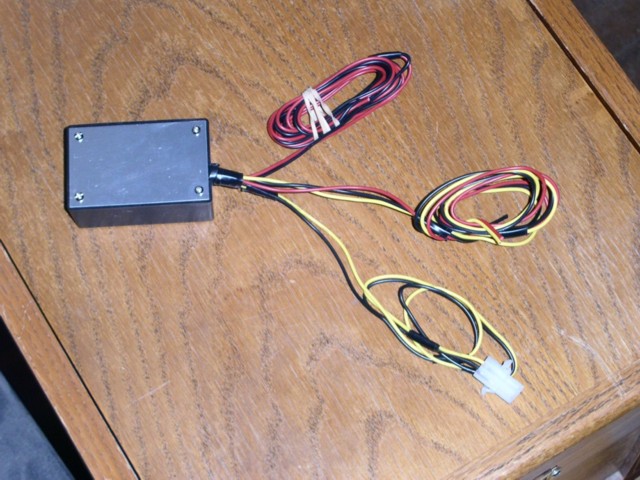
There are three sets of wires:
- The Red/Black bundle is for power/ground and should get power from a line that is hot when the ignition switch is turned on.
- The Red/Yellow/Black bundle goes to the Hall Effect sensor.
- The Yellow/Black bundle goes to the LED assembly. The 12V LED assembly inserts into the dash panel from the front, so I installed a 2-pin connector (Radio Shack P/N 274-222, includes both male and female connectors) between the LED and the module so that I could disconnect the module from the LED to remove the dash panel (Hint: Don't install the connector on the LED lead wires until after you install the LED into the dash panel.
The schematic shows how colored wires on the Hall Effect sensor and LED assembly match up to the wiring bundles.
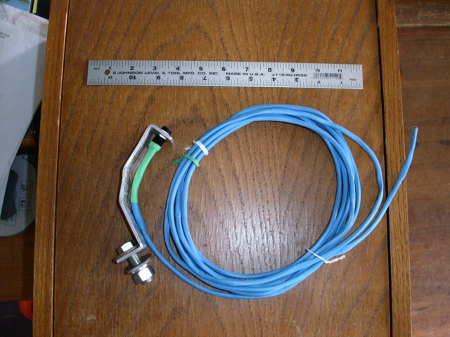
Sensor assembly:
The Hall Effect sensor is a threaded barrel, a little less than 1/2" in diameter with three wires leaving the back. I extended the wires to about 12 feet and applied heat shrink to the entire cable assembly, up to and including the back end of the sensor. I made a bracket of of 1 1/4" x 1/8" aluminum stock (the transfer case is aluminium and I wanted to avoid electrolysis). I bent the bracket by clamping it in a vise and beating it to into shape, with lots of trips to the truck to check the fit. A 1/2" bolt attaches the bracket to a hole in the transfer case on our F-250. I drilled pairs of holes in three places on the bracket so that I could secure the sensor cable with wire ties.
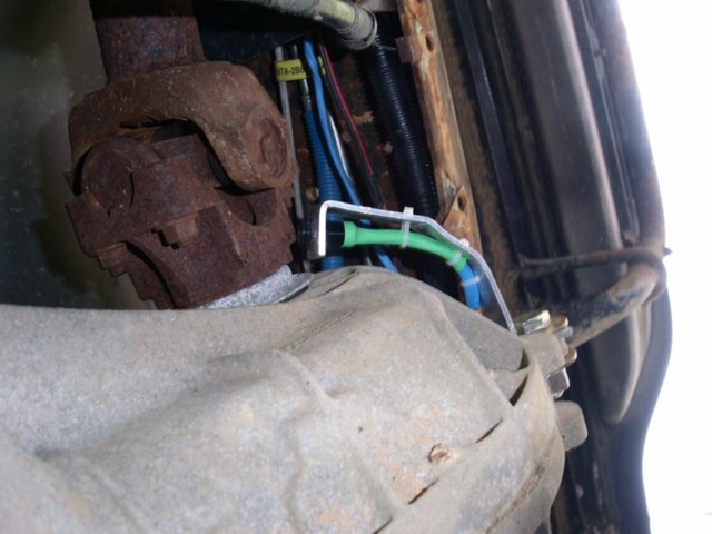
Installation on truck:
This is the transfer case (the left side of the picture is the toward the front of the truck) prior to installation of the sensor, with the skid plate under the transfer case removed (if you remove only the front bolt and loosen the rear bolt on the right side of the vehicle, and remove both bolts on the left side of the vehicle, the skid plate will swing out of your way to work). The place on the joint where I'm sensing are some "points" between the U-joint nuts and the whitish metal ring in front of the transfer case. The bracket attaches to the bottom hole on the left side of the transfer case (right side of the picture) where the case halves join.

Here is the installed bracket. Note the wire ties looping through the bracket to secure the sensor cable (blue).
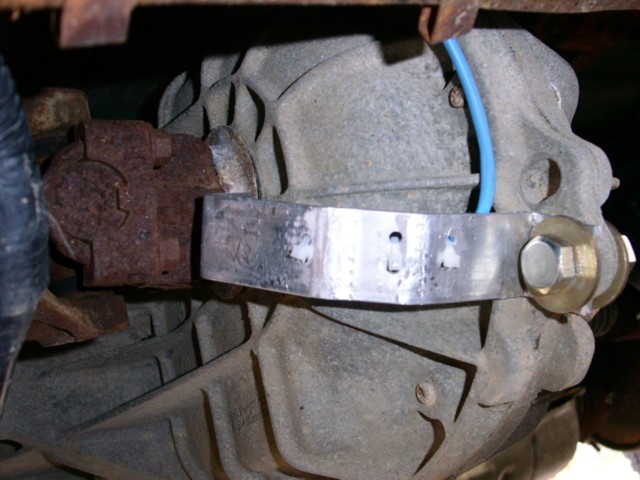
Here is another view, from the "side" of the bracket (below and to the right of the transfer case) showing the bracket, sensor, and cable. Next to the end of the sensor, you can see the "point" I'm sensing on. Beyond the transfer case, you can see the sensor cable routing toward the front of the truck.
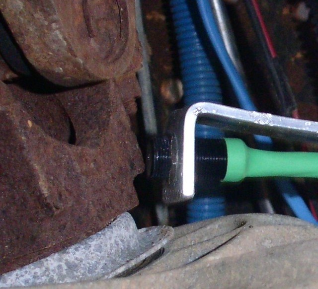
This is a zoomed view showing the sensor clearance, which is set close to reliably sense rotation. I didn't measure the clearance, but I think it's about 1/16". Note that the "point" doesn't cross the center of the sensor. All it has to do is alter the sensor's reference magnetic field, so alignment is not critical. There's probably is a tradeoff between alignment and clearance, where closer centering may permit more clearance. This is where my crudely-constructed bracket placed the sensor, and it works. A bit of Locktite on the sensor threads (on both sides of the bracket) would be a good idea.
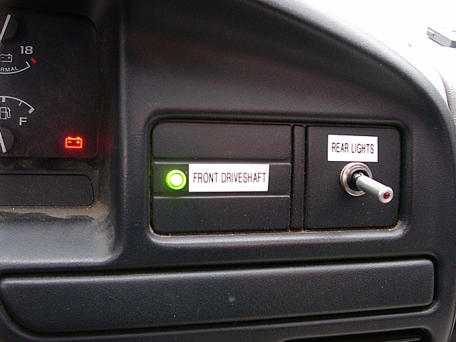
LED mounted in dash:
The ignition switch is turned on but the engine is not running (ergo the battery light).
How does it work?
After driving the vehicle for a few days, it seems to work fine. The real surprise has been how much variation there is in what it takes to unlock the front hubs. The owners manual for the truck gives the following procedure for going from 4WD to 2WD:
- Put the transmission in Neutral (It's an automatic).
- Move the transfer case stick to 2WD.
- Put the transmission in Reverse and back up at least 6 feet.
We're seeing variations between having to just backing up and having to back up then go forward to unlock the hubs. The current hubs are only about a month old so the variation is strange, but the device does give a positive indication of whether the hubs are locked or not.
Here's a video of the LED during operation (AVI format, 1.6MB, 5 seconds) . The video starts with the vehicle in 4WD and stopped, the the vehicle moves forward for a few seconds. The LED flashes when the vehicles moves with the front hubs locked. The shaking is because our driveway is rather rough.
Other stuff:
I'm a bit concerned about the aluminum sensor bracket. The one shown is my second try, after the first one broke while adjusting it for fit. Aluminum develops stress fractures when bent without heating and the current one may eventually weaken. Looking back, I should have either heated the aluminum before bending or made the bracket from steel.
It was really hard to find a place to tie into +12V that isn't on all the time. While Ford did a really nice job is wiring our 1997 F-250, they didn't make life easy for adding switched accessories. If you have a truck of this era, there's a connector (unused in our truck) branching from the cable hock for the radio that contains both a switched power source and a ground. Ours was taped to the cable hock in the area of the cigarette lighter.
I was originally going to use a Red/Green bipolar LED that would glow green when the front shaft was stationary and glow red when it moved. It would have been a nicer touch, but I was really dissatisfied with the results when I started breadboarding the circuit. They're not very bright and burn up easily, I think the Radio Shack 12V LED assembly was a much nicer overall solution.
Thanks to Rob Paisley for the basic circuit (see the Controlling Circuits For LM555 Timers section). I was part way through (badly) designing a solution when I happened into this. I used "Circuit #1" with only minor changes. I also used his calculators to work out resistor and capacitor values, which allowed me to reduce the number of individual component values required. He's created a truly valuable reference.
Updates:
April 2005. My spouse tells me that back in February, at least one of her hubs engaged while driving in 2WD on dry ground, pulling into her workplace. She hadn't used 4WD for many months. The steering started "plowing", then she noticed that the indicator was flashing continuously. She had to go to a parking lot and make a few moves to disengage it. And on locking hubs only 6 months old. Maybe some maintenance is in order. I had wondered if this thing would ever really be of any value. Now I'm sure. She'll keep a log from now on so we can be better informed next time we come to replacement.
The place that previously replaced the hubs told us about a service bulletin from Ford recommending that the vehicle be driven in 2WD with the front hubs locked for about 250 miles to "loosen" up bearings in the transfer case. Apparently, the problem is often that vehicles seldom driven in 4WD experience tightness in the transfer case mechanism that can cause the front shaft to move enough to lock one or both of the front hubs. After driving about 500 miles with the front hubs engaged, the problem is greatly reduced.
Disclaimer. Any and all opinions expressed on this page are solely those of the author. The author accepts no responsibility for the accuracy of data provided on this web site, nor does the author accept any responsibility for the use and /or misuse of information provided on this web site. It is the full and sole responsibility of the user to determine whether and/or how best to use the information provided within their own circumstances, and it is the full and sole responsibility of the user to accept any and all benefits and/or consquences of their actions. Please see my Privacy Policy.
Copyright 2001-2009, Tim Sharpe. You are free to use this information for personal, non-commerical use without restriction. All rights reserved for commerical, organizational, or government use. Questions or comments to tim@beaststwo.org. Flames to /dev/nul.
12045 visits since July 14, 2008